Excerpt form the GMP Compliance Adviser, Chapter 3.J.6 Design qualification (DQ)
The evaluation of the individual phases can be concluded with a "phase report". For different tasks, different deadlines for the DQ can therefore result. In the case of extensive projects, it makes sense to summarize the completed DQs of the individual tasks in an overall report.
For so-called fast-track projects the 2-stage alternative with overlapping phases is chosen very often (see Figure 3.J-9) to avoid long interruptions in the planning phase. For example, in a multi-story building it is possible that the DQ for the layout is complete for the lower levels while the detail design of the upper levels is still ongoing. Special attention should be paid to the critical interfaces between the levels.
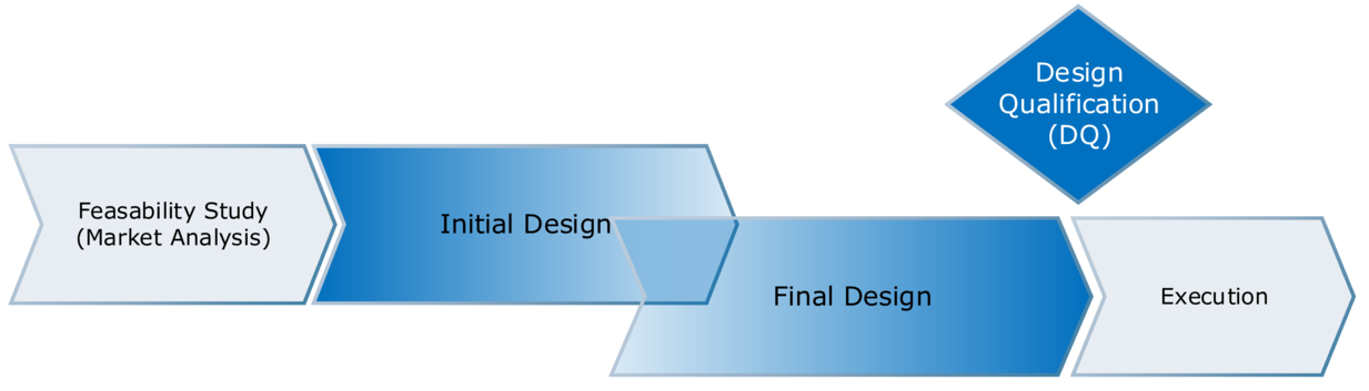
Figure 3.J-9 Two-phase design
With the 3-phase alternative (see Figure 3.J-10), which is portrayed as the standard method for various project management templates, interim reports are also prepared. DQ is not actually performed until after the detail design stage.
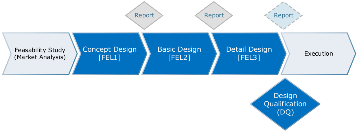
Figure 3.J-10 Three-phase design (FEL – Front-End-Loading – in the area of project management this refers to the practice of establishing a higher level of work at the individual stages with reports for each phase. This serves to reduce the effort associated with late stage changes.)
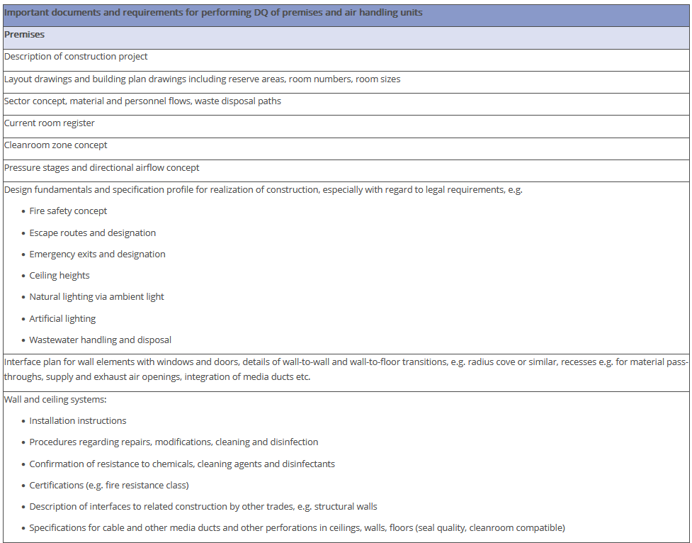
All documents are to be subjected to DQ which form the basis of the construction work for the manufacturing facility and which are to be reflected in the tender process for the construction of the premises and AHU systems.
During execution of DQ it is to be recorded if the document is
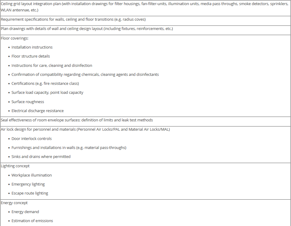
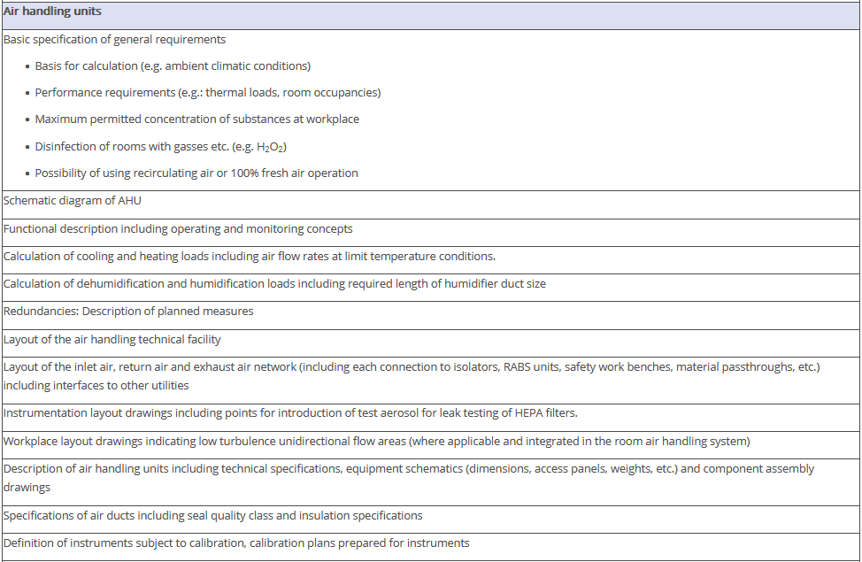
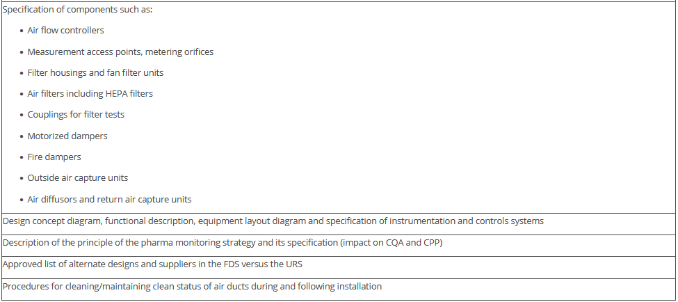
The overview in Figure 3.J-11 does not claim to be comprehensive, nor are all the items listed absolutely necessary. Some of the items shown have no direct connection with the manufacture of pharmaceutical products but deal with general or legal requirements. For example, the roughness of the floor has an influence not only on cleanability, but also on occupational safety (slip resistance), and the fire protection concept is a purely technical safety requirement. The decision as to the extent to which these points are included in the qualification document is the responsibility of the manufacturer.
Figure 3.J-12 Figure 12 IQ checklist for premises and AHU
Important documents and requirements for performing DQ of premises and air handling units |
---|
Premises |
Description of construction project |
Layout drawings and building plan drawings including reserve areas, room numbers, room sizes |
Sector concept, material and personnel flows, waste disposal paths |
Current room register |
Cleanroom zone concept |
Pressure stages and directional airflow concept |
Design fundamentals and specification profile for realization of construction, especially with regard to legal requirements, e.g.
|
Interface plan for wall elements with windows and doors, details of wall-to-wall and wall-to-floor transitions, e.g. radius cove or similar, recesses e.g. for material pass-throughs, supply and exhaust air openings, integration of media ducts etc. |
Wall and ceiling systems:
|
Ceiling grid layout integration plan (with installation drawings for filter housings, fan-filter-units, illumination units, media pass throughs, smoke detectors, sprinklers, WLAN antennae, etc.) |
Requirement specifications for walls, ceiling and floor transitions (e.g. radius coves) |
Plan drawings with details of wall and ceiling design layout (including fixtures, reinforcements, etc.) |
Floor coverings:
|
Seal effectiveness of room envelope surfaces: definition of limits and leak test methods |
Air lock design for personnel and materials (Personnel Air Locks/PAL and Material Air Locks/MAL)
|
Lighting concept
|
Energy concept
|
Air handling units |
Basic specification of general requirements
|
Schematic diagram of AHU |
Functional description including operating and monitoring concepts |
Calculation of cooling and heating loads including air flow rates at limit temperature conditions. |
Calculation of dehumidification and humidification loads including required length of humidifier duct size |
Redundancies: Description of planned measures |
Layout of the air handling technical facility |
Layout of the inlet air, return air and exhaust air network (including each connection to isolators, RABS units, safety work benches, material passthroughs, etc.) including interfaces to other utilities |
Instrumentation layout drawings including points for introduction of test aerosol for leak testing of HEPA filters. |
Workplace layout drawings indicating low turbulence unidirectional flow areas (where applicable and integrated in the room air handling system) |
Description of air handling units including technical specifications, equipment schematics (dimensions, access panels, weights, etc.) and component assembly drawings |
Specifications of air ducts including seal quality class and insulation specifications |
Definition of instruments subject to calibration, calibration plans prepared for instruments |
Specification of components such as:
|
Design concept diagram, functional description, equipment layout diagram and specification of instrumentation and controls systems |
Description of the principle of the pharma monitoring strategy and its specification (impact on CQA and CPP) |
Approved list of alternate designs and suppliers in the FDS versus the URS |
Procedures for cleaning/maintaining clean status of air ducts during and following installation |
This Text is an excerpt form the GMP Compliance Adviser, Chapter 3.J.6 Design qualification (DQ)
Simplify your GMP business! With the GMP Compliance Adviser - the most comprehensive GMP online knowledge portal,
used by more than 10.000 professionals in over 50 countries.
The GMP Compliance Adviser is divided into two parts:
You might also be interested in the following articles